Specifying Line Inductors for Power Converter Noise Filters
2019/02/05
The performance over the full frequency range can vary significantly between different component suppliers for parts with the same nominal characteristics. The variation in inductor performance is examined in this whitepaper.
Abstract
Inductor–capacitor (LC) filters are commonly used at the input and output of switched-mode power converters to reduce reflected ripple current and output noise, and to meet electromagnetic compatibility (EMC) limits for radiation and susceptibility. While the required filter inductor value can be calculated easily, actual inductor performance across the full frequency range can vary significantly between component suppliers, even for parts with identical nominal specifications. These variations can lead to poor noise attenuation and increased conducted or radiated interference. This whitepaper examines the impact of inductor performance differences.
Introduction
Most modern DC power converters, including all isolated DC/DC converters, use a switched-mode topology, where external DC voltages are switched at high frequency to generate a square-wave AC signal for the isolation transformer. The transformer output is then efficiently rectified back to DC, with minimal losses. However, a key drawback of switched-mode designs is that the high-speed switching generates high-frequency ripple on both the input and output lines, along with conducted and radiated noise spikes that can interfere with nearby equipment. As power converters evolve to operate at increasingly higher frequencies with faster switching transitions, the resulting noise spectrum becomes broader and more challenging to suppress.

Fig. 1: External LC filters reduce output ripple and noise
LC Filters Help Reduce Output Noise
Most commercial power converters include basic internal filtering to limit ripple and noise to around 1% peak-to-peak of the DC output. While this is sufficient for many applications, more sensitive systems may require lower noise levels. In such cases, a straightforward solution is to add an external LC filter (Figure 1).
The inductor impedance is theoretically zero at DC, and the capacitor impedance is infinite, so the desired DC output remains unaffected. However, as frequency increases, the inductor impedance (ZL) rises while the capacitor impedance (ZC) decreases, resulting in a growing 'voltage divider' effect.
The corner frequency fc is defined by the following equation:


Fig. 2: An external filter with parasitic elements added
As the equation shows, the corner frequency can be lowered by increasing the inductance, the capacitance, or both. Typically, fc is set to one-tenth of the converter’s switching frequency to achieve effective attenuation.
Although selecting a filter corner frequency to effectively reduce ripple at the converter’s switching frequency is straightforward, predicting the attenuation of noise spikes—comprising a broad spectrum of harmonic frequencies—is more difficult. This is because, at a certain frequency where ZL and ZC become equal, the LC network may begin to resonate, potentially amplifying noise instead of attenuating it. Beyond the resonance point, some noise attenuation remains, but parasitic effects begin to dominate.
For instance, the inductor’s self-capacitance creates another resonance peak at a much higher frequency. This capacitance can also allow high-frequency noise to bypass the inductor. At these higher frequencies, inductor core losses increase, and the AC resistance of the wire rises due to the skin effect. Additionally, the capacitor begins to behave more like a resistor as its impedance drops below its equivalent series resistance (ESR).
The capacitor’s equivalent series inductance (ESL) further contributes to high-frequency behavior. When these parasitic elements are considered, the simple LC filter shown in Figure 1 more accurately resembles the model illustrated in Figure 2.
Parasitic Effects in Inductors Change Noise Attenuation Performance
Using LLOSS 1 and LLOSS 2 along with RLOSS 1 and RLOSS 2 is basic method for modeling frequency-dependent core losses in the circuit. Different LLOSS values result in different impedances, which in turn enable the corresponding resistive elements RLOSS 1 and RLOSS 2 to take effect at various frequencies. Additional LLOSS/RLOSS networks can be added to improve model accuracy, but the component values are difficult to extract from typical inductor datasheets. As a result, creating a complete model for a specific inductor and core generally requires empirical measurement.
More LLOSS/RLOSS networks can be added to make the model more accurate, but component values are difficult to compute from inductor data sheet information. Thus, for a complete model for a particular inductor and core, values must be found empirically.
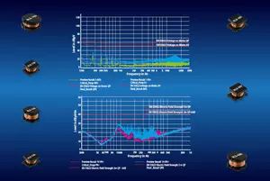
Figure 3 shows ...
More LLOSS/RLOSS networks can be added to make the model more accurate, but component values are difficult to compute from inductor data sheet information. Thus, for a complete model for a particular inductor and core, values must be found empirically.
Figure 3 shows ...