ムーアの法則、より正確には彼の予測は、複雑なIC内のトランジスタ数が約1年ごとに倍増するというものでした。ゴードン・ムーアは1965年に一般誌でこの声明を発表し、当初は10年先までを見据えたものでした。
彼は、その年のIC内に約50個のコンポーネントが搭載されていたことから、1975年には6×6mmのダイ上に65,000個が搭載される可能性があると予測しました。彼の予測はほぼ正確であり、1976年に発売されたIntel 8086は3.2µmプロセスを使用して29,000個のトランジスタを搭載していました。ムーアはその後、2年ごとに倍増するという見積もりに修正しました。複雑さの成長ペースはその後遅くなりましたが、TSMCの2nmプロセス(N2)は2025年後半に量産化される予定であり、特徴サイズが1600倍も縮小するという驚異的な進歩です。
2025年現在、コンシューマー/デスクトップクラスのマイクロプロセッサの最新記録は、Apple社のM3 Ultraが保持しており、デュアルダイ設計で約1840億個のトランジスタを実現し、5nmプロセスで製造されています。このシステムオンチップ(SoC)はそれぞれ420mm²の面積を持つ2つのダイで構成されています。3Dトランジスタやダイスタッキングなどのプロセス革新により、1mm²あたりの処理能力は指数関数的な成長傾向を維持しています。

図1:ムーアの法則の実例:主要プロセッサの登場年およびトランジスタ数
電源 vs. 負荷:なぜ負荷の進化がの方が早いのか
電力ソリューション、電源、または電力消費、エネルギー効率、エネルギー貯蔵に関連する分析の観点からシステム(またはシステムの集合)を評価する際、電源(ソース)と負荷(ロード)を区別することが役立ちます。これは基本的には、電源装置と、それらが供給する電力を消費する最終負荷とを分けて考えるとこうことになります。電源と負荷を、互いに「通信する」独立したブラックボックスと考えてください。以下の図は、システムのブロック図形で概念的に分解したものを示しており、特にコンピューティングまたはサーバーのようなアーキテクチャで、典型的な電源と負荷の区別を強調しています。

図3:電源と負荷を分離するシステムブロック図(PowerRox提供 [1])
この区別は、エンジニアリング、製造、サプライチェーンの変数に影響される多数のコンポーネントで構成された複雑なシステムにおける技術進歩のペースを検討する際に特に重要です。トランジスタ数、電力密度、または
エネルギー効率に関わらず、指数関数的な改善の傾向は、電源側よりも負荷側により強く関連しています。一般的に磁気部品、パワートランジスタ、および
エネルギー貯蔵で構成される電源側コンポーネントは、低電圧半導体と比較してより遅いペースで進化する傾向があります。
なぜ従来のPoLコンバータトポロジーでは追いつけないのか
原則として、PoLコンバータで使用される変換トポロジーは数十年にわたってほとんど変化していません。
降圧、昇圧、および昇降圧回路が標準として使われ続けており、半導体スイッチ、ダイオードまたは同期整流器、インダクタ、およびコンデンサを使用し、パルス幅または周波数変調によって制御を実現しています。コアトポロジーは変わっていませんが、スイッチは静的および動的損失が低くなり、より高い周波数で動作するように進化してきました。インダクタのコア材料は損失を減らすために徐々に改良され、コンデンサ技術も進歩してきました。これらの改良によって全体的に効率が向上し、より高い電力密度が可能になり、同じ負荷と温度上昇でもPoLコンバータをより小型化できるようになりました。しかし、この進歩はムーアの法則に従っておらず、電力コンバータは依然として基板スペースの大きな部分を占めています。
PoLコンバータのサイズについての問題の一因は、従来、ディスクリート部品が基板上でほとんど統合されずに使用されてきたことにあります。これは単純に、PoLコンバータが電力変換器であり、必然的に熱を放散するためであり、温度上昇を低く抑えるために大きな部品が必要だったという事情があります。さらに、インダクタとそのコアは嵩張るディスクリート部品以外の形で製造することが難しく、フェライトコア技術も数十年にわたってわずかな進歩しか遂げていません。これは、最小限必要なコイル巻数を確保しなければならず、さらに過熱することなく高い電流に耐えるために十分な厚さが必要であることを意味します。そして、その結果嵩張るコンポーネントとなります。同じコアの磁束密度と出力リップル電流に対して、スイッチング周波数が上がると必要な巻数は減少しますが、コアとPoLコンバータのスイッチング損失も増加するため、追加の熱を放散するためにより大きなPoLが必要になります。これらすべてが意味するのは、プロセッサとは異なり、PoLコンバータのサイズを小型化すると直接的に熱問題につながる傾向があり、全体的な利点が制限されるということです。
創意工夫で進化に追いつく
負荷のパワーバジェットが電源の供給能力の増加よりも速く減少しているため、ムーアの法則に追いつくには、単に大きな電源を設計するのではなく、パワーバジェットを削減することに焦点を当てる必要があります。 インテリジェントパワーマネジメント(IPM)技術は、コンピュータシステムやデータセンターにおける電力分配と使用を最適化するのに役立ちます [3]。
この考え方の転換には以下のような取り組みが含まれます。
- 「常時オン」から「常時利用可能」な電力アーキテクチャへの移行
- ピークシェービング:定常状態の電力を最適化しながら高出力ピークを処理するためのエネルギー貯蔵の使用
- 負荷遮断/統合:未使用のサブシステムをオフにして電力効率を向上
- 電力割り当ての最適化:最悪のシナリオに対して電源を過剰設計することを避ける
多様なアプリケーションに対応する柔軟なパワーモジュール
負荷点コンバータモジュールは標準的な入力範囲に従わず、必要な出力は約0.5V~3.3V、あるいは従来の設計では5Vまで変動することがあります。電流定格も1アンプ未満から数十アンプまで幅広く変動することがあります。パワーモジュールの入力は、12V、5V、3.3Vといった安定化されたバス電源から供給される場合が一般的ですが、9Vなどの中間電圧を使用することもあります。バッテリー駆動デバイスでは、入力はリチウムイオン電池から供給されることが増えており、通常は約3.7Vですが、充電中は4Vを超え、大きく放電すると3V以下になることもあります。あるいは、入力が非安定化電源から供給され、2:1以上の範囲で変動する場合があります。
幅広いアプリケーションに対応するために、RECOMは現在、昇圧コンバータ用に最低0.85V、降圧コンバータ用に最大65Vまでの入力範囲を持つRPおよびRBシリーズの部品を提供しています。すべての製品が調整可能な出力を備えており、0.6Vから35Vまでの出力電圧を必要とするアプリケーションをサポートしています。電流定格は0.5Aから15Aまで対応しています。図6は、利用可能な降圧コンバータの組み合わせをまとめたものです。

図6:RECOMから提供されている幅広い降圧パワーモジュール、入力電圧および出力電流定格
図7は同様に、最大10A定格までのRECOMから入手可能な昇圧パワーモジュールを示しています。RBB5-1.5および
RBB10製品は、出力が入力よりも高くも低くもなる昇降圧タイプであり、これはバッテリー電源からの電力を放電中も安定供給したい場合に有効です。1.5Aまで提供される昇圧コンバータには出力過電圧保護が含まれており、すべての製品が無効時の真の負荷切断機能を備えています。これはスイッチングしていない時に昇圧コンバータを通じて直接的なDC経路が通常存在するため必要な機能です。また、すべての降圧および昇圧コンバータに過温度保護および出力過電流保護機能が備わっています。

図7:RECOMから提供されている昇圧および昇降圧パワーモジュール
電力供給はムーアの法則に追いついたか?
では、パワーモジュールはムーアの法則に追いついたのでしょうか?24V入力、3.3V出力、4AのPoLコンバータを比較するいくつかの例を考えてみましょう。わずか4年前の2018年に、「電力変換の進歩をリードする」とうたわれた製品がありました。フットプリントは33mm×13.6mm、高さ8.8mm、体積3950mm³でした。現在、RECOM
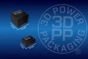
RPX-4.0 は5mm×5.5mmのフットプリントで、高さ4.1mm、容積はわずか113mm³であり、電力密度が35倍に向上しています。興味深いことに、両部品の効率はほぼ同じです。改善はすべて、より高いスイッチング周波数、より小型の部品、および3Dパワーパッケージング®技術によるものです。
もう一つの例は、2Aでの5Vから1.8Vの変換です。古いスルーホール型製品では、フットプリント14mm×7.5mm、高さ10.1mmのものがいまだに見られます。それに対して、RECOM
RPZ-2.0はわずか3mm×3mmで高さ1.1mmであり、電力密度が107倍に向上しています(図8)。フットプリントはほぼ12分の1に縮小され、RECOM部品はマザーボードの片側だけに完全に実装可能で、手動配置とスルーホールはんだ付けの複雑さが排除されています。

図8:従来技術のスルーホール5V to 1.8V/2A PoLコンバータ(左)とRECOM RPZ-2.0(右)の比較(サイズはmm単位、実寸)
明確な価値提案
旧来のオープンフレームDIPスタイルのPoLコンバータでは、ユーザーが同じコンポーネントをマザーボードに直接組み立てられることが多く、購入したモジュールの価値が疑問視されることがありました。省スペースのSIPタイプであっても、マザーボード上で既に用いられているコンポーネント形式や実装技術で簡単に再現できてしまう状況でした。しかし、3Dパワーパッケージングを使用したパワーモジュールは、標準のマザーボード製造方法では経済的に再現することができません。そのため、これらのモジュールは現在、ユーザーが自作を検討しない標準部品(抵抗器やコンデンサなど)と同様の扱いを受けています。コンパクトなサイズにより、他のコンポーネントの周囲や下に容易に取り付けることができ、現在採用されている高度に自動化された製造プロセスにより、コスト削減と信頼性向上を実現しています。
まとめ
電源ソリューションはムーアの法則やMEMSスケーリングのペースに完全には追いつかないかもしれませんが、電源と負荷の間のギャップは急速に縮まっています。インテリジェントな電力管理、エネルギー貯蔵、そして3Dパワーパッケージング®のような先進技術により、現在のパワーモジュールは従来の個別ソリューションをはるかに超える電力密度を提供しています。これらの革新により、現代の性能要求に対応するコンパクトで効率的かつスケーラブルな設計が可能になります。加えて、自動化によるコスト削減と、ハンドヘルド機器からサーバーボードまであらゆるものをカバーするRECOMの幅広いポートフォリオにより、モジュールベースのソリューションは次世代エレクトロニクスにおける明確な選択肢となっています。
参考文献
[1] B. Zahnstecher, “Best Practices for Low-Power (IoT/IIoT) Designs: SEPARATING THE SOURCE-SIDE & LOAD-SIDE ANALYSES,” ECCE 2022 Tutorial, Detroit, MI, October 9, 2022
[2] “DC/DC for GaN,” RECOM Blog, Sep 16, 2022, https://recom-power.com/rec-n-dc!sdc-for-gan-225.html (accessed January 23, 2023)
[3] Data Center Facilities Definitions, "Intelligent Power Management (IPM)," TechTarget, https://www.techtarget.com/searchdatacenter/definitions/Data-center-design-and-facilities (accessed February 24, 2023)


