The Evolution of Robust & Cost-effective, Isolated DC/DC Converters
2023/06/16

The isolated power converter has a rich history of bringing modern, complex, efficient, and SAFE electronics to fruition.
Get the whole Whitepaper now
Introduction
The isolated power converter has played a key role in advancing modern, complex, efficient, and SAFE electronics. Focusing on the key characteristics that determine isolation properties is crucial. These factors influence many of the leading aspects of today’s cutting-edge power supplies, ensuring the continuation of Moore’s Law on the load side while optimizing the manufacturing, cost, and reliability of critical components such as magnetics. These properties also enable the adoption of advanced packaging techniques on the supply side.
A Brief Overview of Isolated DC/DC Converters
The isolated DC/DC converter has enabled numerous applications that would not otherwise be possible, including medical power supplies, high-speed communication buses, offline power solutions, motor drives, and high-voltage use cases.
Perhaps the most significant contribution of isolated DC/DC converters is the isolation itself. The ability to SAFELY process high voltages and/or large amounts of power has been a crucial development in power electronics, benefiting society in ways that may go unnoticed. While many people may not fully appreciate these enabling technologies, they undoubtedly benefit from them in their daily lives. As power electronics engineers (or related fields), we are often the unsung heroes who “secretly” make electronics function—often seen as “black magic” or unknown to the end user.
First, let’s define what isolation is and how it applies to DC/DC converters. Electrical (or galvanic) isolation refers to the physical separation of conductors to prevent the direct flow of current between them [1]. A quick way to test for any level of isolation in a system is to evaluate the ground potentials between two targets. The grounds between isolated circuits should have independent (floating) potentials. Beyond safety, there are several practical applications of floating grounds in DC/DC converters, which we will explore later.
Power conversion circuits use a variety of isolation techniques, and we will review the most relevant ones here. The classification of isolation depends entirely on the physical isolation techniques used, typically achieved through transformer assembly/construction and physical spacing. The table below provides a comprehensive overview of isolation in DC/DC converters and their implementation.
It is important to note that the requirements and aspects of isolation are governed by various industrial and safety standards, which can vary significantly depending on the application and geographical location. Therefore, it is crucial to identify any safety and certification requirements for your system early in the design process. Thorough research into the specific requirements of the application is essential, as factors such as metrics, spacings (in both 2D and 3D), isolation levels, and verification test methodologies can vary widely. These differences can often determine whether the development proceeds smoothly or faces unexpected cost and time overruns.
For example, the excerpt below outlines the voltage spacing requirements for uninsulated conductors from IPC-9592B. It specifies minimum spacing based on conductor potentials and also highlights that creepage and clearance requirements in a related standard (IEC 60950 in this case) may be more stringent and should take precedence. Supporting medical and/or high-reliability applications also requires adhering to many application-specific guidelines and requirements.

Fig. 1: IPC-9592B Uninsulated Conductor Voltage-Spacing Requirements Excerpt [3]
While isolation is commonly achieved through transformer construction, it can also be implemented using other methods, especially for smaller signals (e.g., control feedback, digital communications, etc.). A common approach is isolating communication buses, such as CAN-bus in automotive and industrial applications, by using a small, isolated DC/DC converter or even capacitive isolation for digital signals. Small-signal feedback from an isolated power converter's output can be fed back to the input via an optoisolator. The optoisolator converts the signal's electrical energy to optical and then back to electrical, passing along critical control information while preserving galvanic isolation between the input and output.
Modern advancements in transformer construction, materials, 3D power packaging (3DPP) techniques, and novel manufacturing processes have significantly improved this area. Higher levels of reinforced insulation, combined with improved assembly techniques, allow designs to meet isolation requirements while reducing the overall size. These improvements also leverage automated manufacturing processes, which enhance quality and reliability. Furthermore, they take advantage of economies of scale, ensuring that robustness and power density enhancements do not increase costs. A prime example of this progress is how manually-wound toroids are now automatically controlled by implementing a planar structure that integrates windings into printed circuit boards (PCBs) and incorporates the magnetic core materials into the surrounding geometry.
Perhaps the most significant contribution of isolated DC/DC converters is the isolation itself. The ability to SAFELY process high voltages and/or large amounts of power has been a crucial development in power electronics, benefiting society in ways that may go unnoticed. While many people may not fully appreciate these enabling technologies, they undoubtedly benefit from them in their daily lives. As power electronics engineers (or related fields), we are often the unsung heroes who “secretly” make electronics function—often seen as “black magic” or unknown to the end user.
First, let’s define what isolation is and how it applies to DC/DC converters. Electrical (or galvanic) isolation refers to the physical separation of conductors to prevent the direct flow of current between them [1]. A quick way to test for any level of isolation in a system is to evaluate the ground potentials between two targets. The grounds between isolated circuits should have independent (floating) potentials. Beyond safety, there are several practical applications of floating grounds in DC/DC converters, which we will explore later.
Power conversion circuits use a variety of isolation techniques, and we will review the most relevant ones here. The classification of isolation depends entirely on the physical isolation techniques used, typically achieved through transformer assembly/construction and physical spacing. The table below provides a comprehensive overview of isolation in DC/DC converters and their implementation.
| Isolation Grade Class | Description | Example Use Case |
|---|---|---|
| Functional | The output is isolated, but there is no protection against electric shock | 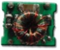
Ring Core Transformer with Functional Isolation |
| Basic | The isolation offers shock protection as long as the barrier is intact | 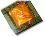
Bobbin Transformer with Basic Isolation |
| Supplementary | An additional barrier to basic, required by agencies for redundancy | 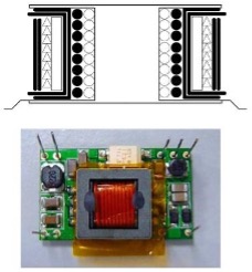
Example of a Reinforced Transformer Construction with a Basic and Supplementary Layer of Insulation (shown as the thick black lines in the diagram |
| Reinforced | A single barrier equivalent to two layers of Basic insulation |
Table 1: Common Isolation Grade Overview Table, From “Understanding isolation in DC/DC converters” Blog [2]
It is important to note that the requirements and aspects of isolation are governed by various industrial and safety standards, which can vary significantly depending on the application and geographical location. Therefore, it is crucial to identify any safety and certification requirements for your system early in the design process. Thorough research into the specific requirements of the application is essential, as factors such as metrics, spacings (in both 2D and 3D), isolation levels, and verification test methodologies can vary widely. These differences can often determine whether the development proceeds smoothly or faces unexpected cost and time overruns.
For example, the excerpt below outlines the voltage spacing requirements for uninsulated conductors from IPC-9592B. It specifies minimum spacing based on conductor potentials and also highlights that creepage and clearance requirements in a related standard (IEC 60950 in this case) may be more stringent and should take precedence. Supporting medical and/or high-reliability applications also requires adhering to many application-specific guidelines and requirements.

Fig. 1: IPC-9592B Uninsulated Conductor Voltage-Spacing Requirements Excerpt [3]
While isolation is commonly achieved through transformer construction, it can also be implemented using other methods, especially for smaller signals (e.g., control feedback, digital communications, etc.). A common approach is isolating communication buses, such as CAN-bus in automotive and industrial applications, by using a small, isolated DC/DC converter or even capacitive isolation for digital signals. Small-signal feedback from an isolated power converter's output can be fed back to the input via an optoisolator. The optoisolator converts the signal's electrical energy to optical and then back to electrical, passing along critical control information while preserving galvanic isolation between the input and output.
Modern advancements in transformer construction, materials, 3D power packaging (3DPP) techniques, and novel manufacturing processes have significantly improved this area. Higher levels of reinforced insulation, combined with improved assembly techniques, allow designs to meet isolation requirements while reducing the overall size. These improvements also leverage automated manufacturing processes, which enhance quality and reliability. Furthermore, they take advantage of economies of scale, ensuring that robustness and power density enhancements do not increase costs. A prime example of this progress is how manually-wound toroids are now automatically controlled by implementing a planar structure that integrates windings into printed circuit boards (PCBs) and incorporates the magnetic core materials into the surrounding geometry.
Impacts of Isolation on Converter Design

The most common figures of merit (FOM) for designing and optimizing power solutions are size, weight, and power (often referred to as SWaP factors). When combined with a cost metric, these are known as SWaP-C factors [4]. Given the varying methods and levels of isolation required by a design, these factors can significantly impact overall SWaP-C, especially in filter components.
Most systems cannot ship without signoff or certification for meeting multiple safety and functional standards. These are not optional features but critical to market acceptance, often introducing additional cost and time into a project development schedule that may not have anticipated the resources needed to support these requirements.
For example, the table in the previous section illustrates the tradeoff between voltage and spacing when packing conductors at different potentials into tight spaces. The isolation grade class determines the number of isolation protection features required, along with their minimum characteristics (e.g., material, thickness, or redundancy) to meet the isolation specification, typically conveyed in terms of voltage level and withstand time for exposure to such voltages while maintaining functionality.
This leads to a typical tradeoff analysis, where shrinking overall solutions to optimize SWaP can increase costs, particularly when more expensive components (such as triple-insulated wire or TIW) are required to meet these specifications in more compact designs.
Other technical factors, such as thermal mitigation and support for wide, high-voltage ranges, may drive the compactness of a solution. As with any engineering development, reasonable compromises must be made between meeting core functional and safety requirements, cost impacts on development schedules and budgets, warranty and reliability needs, and time-to-market (TTM) targets. Given that magnetics manufacturing remains one of the last manual component assembly processes on the production line, it is important to emphasize that shifting as much of this to automation and non-hand-soldered assembly can help optimize crucial elements of SWaP-C and improve the reliability of the design.
At this point, it seems beneficial to provide a quick mapping of isolated solutions to common power topologies and implementations. While a comprehensive overview of topologies is beyond the scope of this paper, the goal here is to give a brief summary of which power conversion topologies support isolation and why.
| Topology | Fundamental circuit | Impacts of isolation/regulation |
|---|---|---|
| Unregulated push-pull (Royer) | 
Unregulated push-pull converter circuit |
|
| Inverting buck-boost (Flyback) | 
Basic Flyback converter circuit |
|
| Half-Bridge (push-pull) | 
Basic Half-Bridge converter circuit |
|
| ... | ... |
|
Table 2: Power Converter Topology Isolation/Regulation Comparison Table
Want to read the whole Whitepaper?
アプリケーション


")


