DC Microgrid Power Supplies: Universal Solutions for Industrial Automation

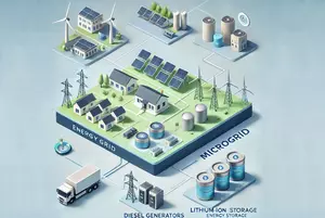
風力タービン、ソーラーパネル、ディーゼル発電機、リチウムイオン蓄電池を含むエネルギーグリッドとマイクログリッドのイラスト
Mains electrical distribution in buildings varies by voltage levels and specifications based on factors like application needs, safety, and history. For AC distributions, nominal voltage and frequency are key, with global standards influencing the different voltage levels.

Get the whole Whitepaper now

Introduction

We are used to the mains electricity coming out of our wall sockets being AC (Alternating Current), but this was not always the case. In the early days of electrification, Direct Current (DC) was also widely implemented. The history of the AC versus DC rivalry between Edison and Tesla is well-documented [1], with Tesla’s AC system ultimately becoming the globally accepted standard. Today’s dynamic industrial landscape demands greater flexibility and efficiency in power supply systems, and DC is making a strong return – especially as many renewable energy technologies, such as solar panels and residential battery systems, inherently operate on DC power.

AC Versus DC Power in Building Distributions

When it comes to mains electrical distributions in buildings, one can find a wide variety of voltage levels, specifications, form factors, and tolerances. The logic for determining the requirements of either an AC or DC distribution is typically based on application needs, safety, economics, historical context, and ideally, practical considerations. Even if we focus solely on AC distributions, there are numerous voltage levels and ranges defined by a wide array of global standards. The most fundamental characteristics that define a voltage bus are its nominal voltage and frequency (while maximum current ratings are more relevant to sizing conductors, infrastructure, and related components). A quick overview of global AC mains [2] is summarized in figure 1.

Global map of power plug types, voltage ranges, and socket standards with safety symbols

Fig. 1: Mains electricity by country and, especially for continental Europe, Public Domain, https://commons.wikimedia.org/w/index.php?curid=8781813

Providing a stable, well-regulated gate voltage supply – independent of the main power supply – is another advantage of isolated DC/DC converters. In typical gate drive circuits, the primary supply generates the gate voltage using either a linear regulator or a bootstrap circuit. Linear regulators, while simple to implement, generally suffer from poor efficiency and high power dissipation, especially when there is a large voltage differential between input and output. This excess dissipation can lead to thermal management challenges, potentially requiring additional heat sinks or active cooling.

Bootstrap circuits, by contrast, use a charge pump mechanism to supply the high-side transistor’s gate voltage in a half-bridge configuration. In such setups, it is critical to size the bootstrap capacitor appropriately to ensure sufficient charge is available to drive the transistor gate throughout the on-time. The duty cycle and switching frequency directly affect performance and can cause voltage droop or instability if not properly accounted for.
RECOM RACM1200-48SAV/ENCラベル
Fig. 2: RECOM AC/DC Power Supply Safety Label (Example)
A close examination of global voltage standards reveals a general range of 100–240VAC at either 50 or 60Hz. This might suggest that a single power supply supporting the entire voltage and frequency spectrum would be universally compatible – but that’s not necessarily the case. See the example safety label for a certified, globally shipping power supply in figure 2.

It may seem natural to want to support as wide a range as possible, but as with anything in life (especially power), there are tradeoffs to consider when optimizing a solution for a specific application or use case. Designs must also include tolerances to account for non-ideal operating conditions. In terms of voltage, this includes protections for overvoltage scenarios (typically for both personal safety and equipment protection), undervoltage conditions (to maximize uptime and protect equipment), and balancing phase currents in multiphase systems. For line frequency, considerations relate to power quality and grid stability.

The specific mechanisms and methods for achieving these protections are beyond the scope of this discussion but are covered in detail in the RECOM AC/DC Book of Knowledge: Practical Tips for the User [3], which is freely available. By applying a common tolerance figure of ±10%, we can define a broad operational range of 90–264VAC and 47–63Hz – commonly seen on power supply safety labels. This example demonstrates how diverse international standards can be consolidated into more universally supported ranges, though it does not explore the motivations behind individual regional mains specifications. Additional support ranges also exist for military and industrial environments, such as the 400Hz standard used in aircraft and shipboard power systems. In three-phase AC configurations, multiple single-voltage sources may be separated by phase angle to maximize power delivery while minimizing current loads.

Ultimately, most end systems and loads will run off of DC power (AC motors being the glaring exception), which is why there are even more standards for DC voltage supplies than AC, though not typically for facilities or building-scale distributions. High voltage is defined as >1,000/1,500V (AC/DC, respectively), though pretty much anything ≥60VDC is considered high voltage for safety purposes (human contact), also known as Safety Extra Low Voltage (SELV).

While no single standard exists (actually, numerous exist worldwide) for what is commonly referred to as the high-voltage data center (HVDC – not to be confused with high-voltage direct current), many standards define distribution architectures in the 300–400VDC range. The logic is: if server/networking hardware and supporting infrastructure are all designed to support a universal AC input with a power-factor-correcting (PFC [4]) AC/DC power supply, then the same equipment can accept the DC voltage derived from the rectified AC waveform – justifying the elimination of a conversion stage (and all the benefits gained by its removal).

24VDC distributions are common in industrial settings with small relays, breakers, motors, and systems optimized for a standard mechanical form factor, such as the DIN rail [5] standard. Other well-known DC distributions include the Universal Serial Bus (USB, 5–20VDC) and Power over Ethernet (PoE, 44–57VDC), which also combine power with data conductors in hybrid cables. The choice of a main distribution voltage for a facility is driven by many factors tied to decisions around capital and operational expenditures (CAPEX/OPEX, respectively) – not simply what equipment needs to plug into it. Safety is almost always a key factor in determining distribution architectures and must be considered based on worst-case scenarios for operator exposure, conductor-to-conductor spacing, and constraints within the operating environment.

Consolidating voltage distribution bus architectures offers several advantages, including streamlined equipment procurement (CAPEX) and more efficient use of equipment and machines (OPEX). The fewer the conversion stages from upstream sources (e.g., utility grid, energy storage, etc.) to the end load (e.g., system, ASIC, motor, etc.), the greater the potential to simplify infrastructure and leverage economies of scale. Commonality can also help mitigate net load dynamics, enabling improved energy efficiency by reducing unpredictability and opening up more opportunities for intelligent power management (IPM [6]) techniques.

A common mains or distribution architecture carries far more benefits than can be comprehensively reviewed here, but a few additional categories are worth recognizing. The ability to maintain a more predictable maintenance schedule and manage fewer part numbers can result in significant savings – both in the short and long term. A reduced number of parts to replace or manage offers several clear advantages, from saving user effort at the point of consumption to lowering overhead and shipping costs for replacements.

As we transition to Smart Buildings and factories of the future, achieving both configurability and agility through common form factors is critical for success. From a quality perspective, systems – particularly components and motors – will have longer lifespans when operating in more constrained, predictable environmental conditions and maintenance cycles. These first-order benefits cascade into a wide range of second-order advantages, depending on how deeply one chooses to analyze the system. For example, a common distribution architecture can reduce the need for costly backup power or energy storage solutions that would otherwise serve as buffers for intermediary voltages. Even a small improvement in the efficiency of input-to-output power commutation – just a few percentage points – can justify substantial CAPEX savings, with benefits extending all the way from the point of load up to the power plant.

Distributed Energy Resources (DER) Change the Landscape

電力系統、再生可能エネルギー、EV、蓄電、建物を接続するマイクログリッド図
The concept of distributed energy resources (DER [7]) is not new, but it is being adopted in a modern context to support the transition to a more sustainable world. The idea centers around having many smaller, modularized utility solution blocks (i.e., source, distribution, conversion, storage, etc.) that are locally confined for control and use – collectively known as a microgrid.

Microgrids composed of DERs are typically defined by their ability to operate fully independently (“stand-alone” or “islanded” mode), while also being capable of functioning in grid-connected scenarios. (NOTE: The term “compatible” is intentionally broad in this context, as compatibility can involve extensive considerations related to hardware and regional regulatory requirements.)

Much of the technology needed to upgrade yesterday’s power grids into tomorrow’s smart grids with intelligent power management already exists and has for many years. However, the macroeconomic momentum required to drive a multigenerational upgrade of utility-scale infrastructure remains elusive—even in many of the world’s most developed nations. Photovoltaic (PV) solar panels, for instance, have been commercially available for nearly 50 years, yet grid infrastructure designed to handle bidirectional power flow remains a relatively new concept. Unfortunately, investment in advanced energy storage technologies tends to lag behind investment on the load side, where systems are evolving faster and becoming more cost-effective.
Graph with different energy sources, including renewable and conventional energy types

Fig. 3: Centralized (left) vs distributed generation (right), Chronological Comparison, Graphic: Bartz/Stockmar, CC BY 4.0

The application of energy storage across multiple use cases – for both critical energy backup and economic optimization of intermittent energy sources (such as wind or solar) – is prompting new thinking around upgrading existing infrastructure and building future-proofed facilities. The modular nature of a DER allows energy storage requirements to be right-sized for specific applications and decoupled from bulk storage needs. This principle should be applied across various aspects of energy storage deployment.

For example, storage can serve a purely economic role by capturing excess renewable energy during periods of high generation and low real-time energy costs, then releasing it when prices rise. In addition to traditional roles like critical energy backup, emerging applications include “peak shaving,” where localized storage handles infrequent energy surges. This approach allows infrastructure – such as “virtual power plants” – to be designed closer to a maximum steady-state rather than an absolute peak, yielding significant CAPEX and OPEX savings.

DERs have the potential to completely upend the economics of electric utilities as we know them today. Traditionally, the time-based relationship of grid energy usage throughout a day follows what is known as a “duck curve” [8], named for the bimodal distribution of demand peaks in the morning and evening, which resembles the shape of a duck’s back. Electrical economics are based on peak demand during these periods, with lower demand in between. But what happens when all devices become “smart” and capable of optimizing their power usage during these mid-day lulls? From a control systems perspective, this introduces a paradox. The once-predictable duck curve can invert – if enough smart loads collectively delay consumption until the lull, their aggregated demand could flip the curve entirely. What implications does this have for the dynamic energy market, where the price of power can shift multiple times per hour based on demand?

The issue of grid economics is ...

Want to read the whole Whitepaper?

アプリケーション