
Redundancy Diode Modules: Reliable Power Through Decoupling
Oct 29, 2026

Redundancy diode modules are used to increase the reliability of DC power systems in industrial automation, control cabinets, communication equipment, and other critical applications. Their main function is to connect the outputs of two or more (N+1) power supplies in parallel to provide fault redundancy or for power sharing while preventing one supply from feeding current back into another. Typical applications include PLC systems, process control, machine automation, safety-related control circuits, telecommunications equipment, and 24 or 48VDC industrial power distribution. Wherever unplanned downtime is costly or unacceptable, redundancy diode modules ensure system power availability.
Table of Contents
Operating Principle
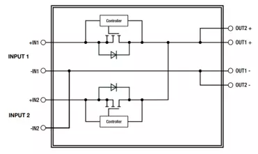
The operating principle is straightforward: each power supply is connected to the load through a one-way decoupling element.
A redundancy diode module serves two main functions:
In short, redundancy diode modules provide a compact and reliable way to build fault-tolerant DC power systems. They protect power supplies from reverse currents, isolate failed units, and keep critical loads running when one supply path is lost. The following examples show typical fault-tolerant arrangements (though by no means exhaustive).
A redundancy diode module serves two main functions:
- Fault isolation & reverse current protection: If one power supply or its upstream supply fails, the redundancy module blocks reverse current into the faulty unit while the remaining supply continues to power the load (Figure 1). This enables full OR-ing redundancy—even if one power supply fails with an output short circuit, the load remains powered up.
- Current combination & power sharing: It combines the outputs of two or more (N+1) power supplies to increase the overall available output current while eliminating the risk of one supply feeding current back into another.
System Design Recommendation
A redundancy diode module is most effective when used as part of a properly designed power architecture. The power supplies should be independently protected, correctly dimensioned, and ideally fed from separate upstream circuits via independent circuit breakers. This ensures that a single upstream fault does not disable the entire DC supply system.In short, redundancy diode modules provide a compact and reliable way to build fault-tolerant DC power systems. They protect power supplies from reverse currents, isolate failed units, and keep critical loads running when one supply path is lost. The following examples show typical fault-tolerant arrangements (though by no means exhaustive).
Redundant DC Power Supply Configurations
Example 1: Fully Redundant Power Supply
This is the classic redundant power supply arrangement where two independent power supply outputs are combined to create a highly fault-tolerant DC supply.
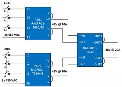
| Type of Fault | Likelihood | Result |
|---|---|---|
| No Fault | 100% max load (960W) | |
| Circuit breaker #1 or #2 nuisance trips | 1 | No change |
| Phase Drop Out | 2 | No change (full power with 2 out of 3 phases) |
| Loose wiring PSU1 or PSU2 DC output | 3 | No change |
| PSU1 or PSU2 shuts down (OTP) | 4 | No change |
| PSU1 or PSU2 fault output open circuit | 5 | No change |
| PSU1 or PSU2 fault output short circuit | 6 | No change |
Example 2: Current Sharing Power Supply
In this example, the outputs of two identical power supplies are combined to double the output current.
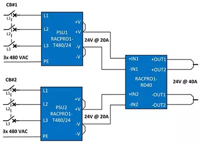
| Type of Fault | Likelihood | Result |
|---|---|---|
| No Fault | 200% max load (960W) | |
| Circuit breaker #1 or #2 nuisance trips | 1 | 100% max load (480W) |
| Phase Drop Out | 2 | No change (full power with 2 out of 3 phases) |
| Loose wiring PSU1 or PSU2 DC output | 3 | 100% max load |
| PSU1 or PSU2 shuts down (OTP) | 4 | 100% max load |
| PSU1 or PSU2 fault output open circuit | 5 | 100% max load |
| PSU1 or PSU2 fault output short circuit | 6 | 100% max load |
Example 3: HV DC Backup Power Supply
This example shows how to incorporate a high-voltage DC backup source (in this case, a bank of 24V batteries) to generate an uninterruptible low-voltage DC supply output.
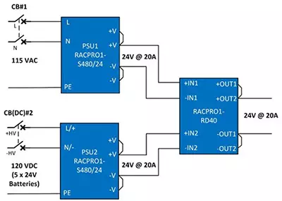
| Type of Fault | Likelihood | Result |
|---|---|---|
| No Fault | 100% load (480W) | |
| Circuit breaker #1 or #2 nuisance trips | 1 | No change (automatic switch to alternate supply) |
| AC Phase Drop Out | 2 | No change (automatic switch to backup HVDC supply) |
| HV DC Drop Out | 3 | No change (AC powered) |
| PSU1 or PSU2 shuts down (OTP) | 4 | No change |
| Loose wiring AC or HV DC input | 5 | No change |
| Loose wiring PSU1 or PSU2 DC output | 6 | No change |
| PSU1 or PSU2 fault output open circuit | 7 | No change |
| PSU1 or PSU2 fault output short circuit | 8 | No change |
Example 4: AC Phase Redundancy
This example shows an arrangement where three single-phase power supplies are each fed from a separate phase from a three-phase supply. As long as at least one phase remains active, the DC supply is guaranteed.
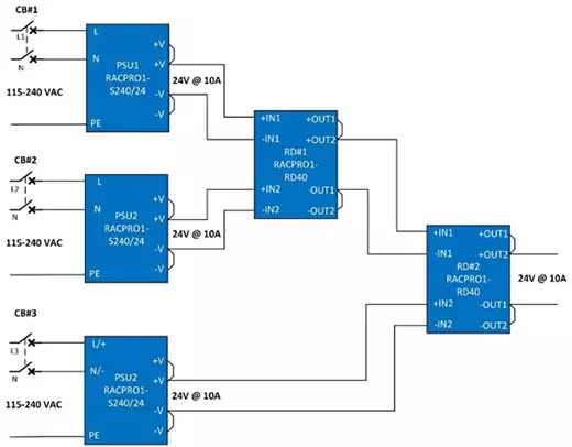
| Type of Fault | Likelihood | Result |
|---|---|---|
| No Fault | 100% load (240W) | |
| Circuit breaker #1, #2 or #3 nuisance trips | 1 | No change |
| 1-out-of-3 AC Phase Drop Out | 2 | No change (powered from remaining 2 phases) |
| 2-out-of-3 AC Phase Drop Out | 3 | No change (powered from remaining phase) |
| PSU1, PSU2 or PSU3 shuts down (OTP) | 4 | No change |
| Loose wiring L1, L2 or L3 input | 5 | No change |
| Loose wiring PSU1, PSU2 or PSU3 DC output | 6 | No change |
| PSU1, PSU2 or PSU3 fault output open circuit | 7 | No change |
| PSU1, PSU2 or PSU3 fault output short circuit | 8 | No change |
Example 5: Fault-Tolerant Battery Charger
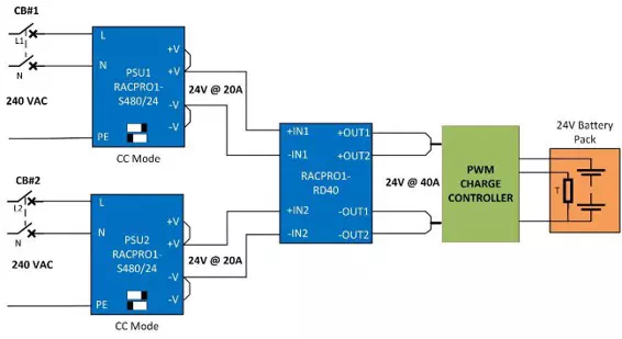
This example shows an arrangement where a two-phase AC power supply is used to fast charge a high-capacity battery. The RACPRO1-S480/24 power supplies are switched to constant current mode to strictly limit the maximum overall output current to 40A. This simplifies the design of the PWM charge controller which needs only to limit the initial charging current until the battery cells are sufficiently pre-charged and then turn on the full fast charge current. If either mains phase or PSU fails, the charging continues but is limited to 20A. The RACPRO1-RD40 also has a 70VDC return voltage immunity, effectively shielding the AC/DC power supplies from battery load dump transients and surges.
Example 6: Vertical Installation
The majority of electrical cabinets have horizontally mounted rails, and many DIN-rail mount power supplies are designed for proper free-air convection cooling only when mounted in the standard vertical orientation.
The RACPRO1 series are the exception, as they can be mounted in any non-standard orientation with only 15% derating—even when mounted horizontally onto vertically aligned rails. They are also significantly narrower than the competition, taking up less space on the rail. These features are especially useful for the tall and narrow cabinets used on telecommunication masts, lighting poles, advertising billboards, small wind generators, and tower cranes.
The RACPRO1 series are the exception, as they can be mounted in any non-standard orientation with only 15% derating—even when mounted horizontally onto vertically aligned rails. They are also significantly narrower than the competition, taking up less space on the rail. These features are especially useful for the tall and narrow cabinets used on telecommunication masts, lighting poles, advertising billboards, small wind generators, and tower cranes.
Conclusion
Building a resilient, fault-tolerant DC power architecture doesn't have to require complex engineering or excessive cabinet space. By implementing active-rectifier redundancy modules like the RACPRO1-RD40, design engineers can eliminate single points of failure, maintain optimal power efficiency, and ensure maximum uptime for critical industrial applications.
Frequently Asked Questions
No. The RACPRO1-RD40 features a wide DC input range of 9–56VDC, meaning 12, 24, 36, or 48VDC systems can all be supported using the exact same module.
The RACPRO1-RD40 has significantly fewer internal components than an AC/DC power supply, making it inherently more reliable. Its operational lifetime expectancy is 268,000 hours at 40°C (over 30 years of continuous operation).
The RACPRO1-RD40 operates at an efficiency of 99.5% at full load (40A), meaning power loss across the module is negligible.
The RACPRO1-RD40 has a no-load power consumption of just 200mW with a 24V supply, keeping losses extremely low across the entire 0% to 100% load range.
The RACPRO1-RD40 uses active rectifiers rather than traditional power diodes, keeping insertion loss to a minimal 140mV.
No. The RACPRO1-RD40 can handle up to 60A for up to 5 seconds, ensuring high inrush currents pass through effortlessly.
No. This function is unnecessary because the input-side AC/DC power supplies are already short-circuit protected. Adding an intermediary SCP function inside the redundancy module would interfere with the correct operation of the power supplies' own SCP mechanisms.
No. The RACPRO1-RD40 is certified for both EN 61000-6-4 Class B emissions and EN 61000-6-2 Class B immunity, ensuring it will not compromise overall system EMC performance.
Applications


| Series | |||||||
|---|---|---|---|---|---|---|---|
| 1 |

|
RACPRO1-RD
Focus
New
|
|
| |||
| 2 |

|
RACPRO1-S240
Focus
New
|
|
| |||
| 3 |

|
RACPRO1-S480
Focus
New
|
|
| |||
| 4 |

|
RACPRO1-T480
Focus
|
|
| |||
| 5 |

|
RACPRO1-T960
Focus
|
|
|